Load HEC-RAS 2D Geometry Layers
Use this tool to extract supported 2D flow-area, mesh, boundary, breakline, and pipe-network geometry from a HEC-RAS geometry or plan HDF.
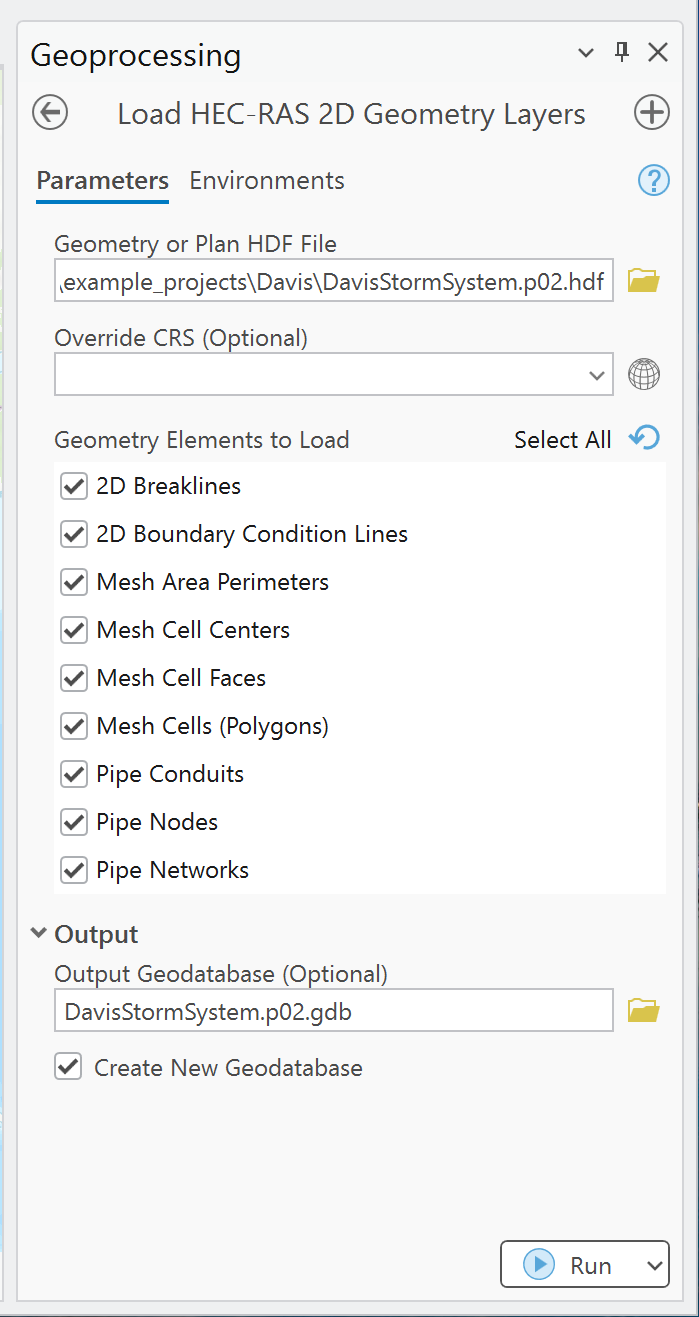
Before you run it
- Select a
g*.hdforp*.hdfthat contains 2D flow-area geometry. - Start with perimeters or cell centers for a quick spatial check.
- Use a local file geodatabase for large models.
- Confirm whether the source model actually contains HEC-RAS pipe-network groups before selecting pipe outputs.
Parameters
| Parameter | Required | Behavior |
|---|---|---|
| Geometry or Plan HDF File | Yes | Reads a HEC-RAS geometry or plan HDF. |
| Override CRS | No | Used only if automatic CRS detection fails; it does not reproject a detected CRS. |
| Geometry Elements to Load | Yes | Multi-select list. Defaults to Mesh Area Perimeters. |
| Output ... | Conditional | One output feature class is enabled for every selected element. Defaults are in-memory paths. |
| Output Geodatabase | No | Persistent file geodatabase destination. |
| Create New Geodatabase | No | Enabled by default; creates/reuses Project.pXX.gdb and a plan feature dataset. |
Available elements
| Element | Geometry | Organized name | Main attributes |
|---|---|---|---|
| 2D Breaklines | Polyline | Breaklines2D |
Name, near/far cell spacing, repeat count, protection radius |
| 2D Boundary Condition Lines | Polyline | BCLines2D |
ID, name, type |
| Mesh Area Perimeters | Polygon | MeshPerimeters |
mesh_name |
| Mesh Cell Centers | Point | MeshCellCenters |
mesh_name, cell_id |
| Mesh Cell Faces | Polyline | MeshCellFaces |
mesh_name, face_id |
| Mesh Cells (Polygons) | Polygon | MeshCellPolygons |
mesh_name, cell_id |
| Pipe Conduits | Polyline | PipeConduits |
Fields are derived from the HDF conduit attributes. |
| Pipe Nodes | Point | PipeNodes |
Fields are derived from the HDF node attributes. |
| Pipe Networks | Polygon | PipeNetworks |
Fields are derived from the HDF network attributes. |
Procedure
- Open Load HEC-RAS 2D Geometry Layers and select the HDF.
- Supply Override CRS only if the tool cannot determine the project projection.
- Select the minimum elements needed for the task.
- Keep mesh-cell polygons off for the first run unless polygon cells are specifically required.
- Choose a file geodatabase or keep automatic geodatabase creation enabled.
- Run the tool and review all messages, especially missing-element notices.
- Overlay perimeters and centers against RAS Mapper or trusted project data before adding more expensive layers.
Performance guidance
Mesh-cell polygons are reconstructed from cell faces. Their cost grows with the number and complexity of cells. For large models:
- Prefer perimeters and centers for overview mapping.
- Add faces only when connectivity/edge geometry matters.
- Request polygons only for analyses that require cell footprint geometry.
- Write to a local file geodatabase rather than the in-memory workspace.
- Process one plan at a time when diagnosing performance or schema differences.
Pipe-network notes
The tool checks for pipe conduit and node groups before extraction. If the source HDF has no supported pipe data, it reports that no data were found and continues with other selected elements. Dynamic HDF attributes are converted to ArcGIS-compatible field names, so punctuation may be replaced and reserved names may receive a suffix.
Common checks
- Compare flow-area count and perimeter extents with RAS Mapper.
- Check a sample of cell IDs and face locations.
- Confirm that breakline and boundary-condition names match the source geometry.
- For pipes, compare node/conduit counts and invert/elevation fields with the HEC-RAS model.
- Confirm that polygon construction did not create unexpected gaps or overlaps before spatial analysis.
See Outputs and naming and the validation checklist.